Many users spend years with a film thickness gauge while their understanding stops at "shine a light, get a number." What happens inside this black box is actually not complicated, and it is worth understanding, because instrument selection, acceptance testing, and troubleshooting anomalous data all depend on a grasp of this principle.
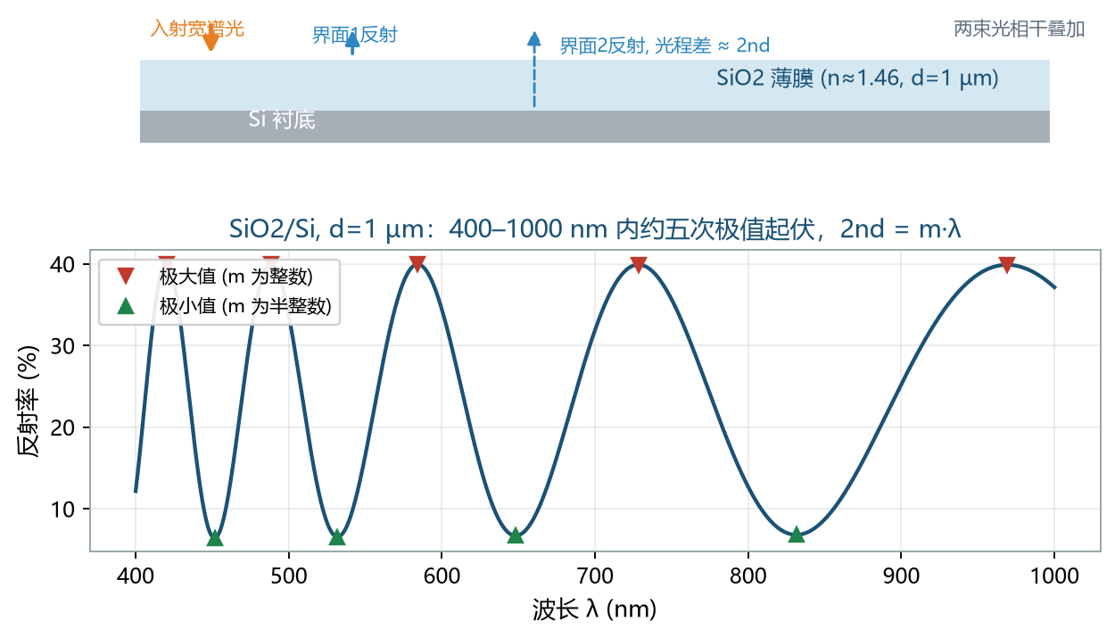
Start with the physics. Broadband light strikes a single-layer film at normal incidence, and part of it reflects at each of the two interfaces, ambient-film and film-substrate. These two reflected beams are coherent and interfere according to their phase difference when they overlap: in phase they reinforce, out of phase they cancel. From the geometry of the optical path inside the film, the optical path difference between the two beams is approximately 2·n·d·cosθ, where n is the refractive index of the film, d is the film thickness, and θ is the refraction angle inside the film.
Interference extrema occur whenever the optical path difference equals an integer multiple of the wavelength; written as an equation, 2·n·d = m·λ. This condition encodes thickness into the reflectance spectrum: for a fixed thickness, the arrangement of extrema across wavelengths is fixed. Measuring the entire reflectance spectrum is therefore equivalent to measuring this arrangement, and the remaining problem is to invert it for d.
Feel it with a real number. Silicon dioxide (n ≈ 1.46) on a silicon substrate, 1 µm thick, at normal incidence: 2nd = 2920 nm. Across the visible band from 400 to 1000 nm, m = 7.3 at λ = 400 nm and m = 2.92 at λ = 1000 nm, so m sweeps continuously from 2.92 to 7.3 and the spectrum shows about five bright-dark oscillations. Clear oscillations with well-spaced extrema — this is the operating regime where a reflectance-based film thickness gauge is most at home.
In a real instrument, the inversion runs in two steps. Step one is a quick estimate: take the FFT (fast Fourier transform) of the spectrum, and the spatial frequency of the fringes corresponds directly to the optical thickness n·d, giving an initial value in milliseconds. Step two is fine fitting: starting from that initial value, a dispersion model solves simultaneously for thickness and refractive index n(λ), and for the extinction coefficient k(λ) when necessary. Neither step can be dropped: FFT is fast but coarse, fitting is accurate but model-dependent.
This two-step design explains two everyday observations. First, why the instrument performs best on smooth, clean film surfaces: high fringe contrast is what makes the FFT peaks sharp. Second, why more complex film stacks mean slower measurements and heavier reliance on prior knowledge: every extra layer adds another set of free parameters to the fit, demanding more data and stronger model constraints. For a stack of five or more layers, without reliable per-layer refractive index inputs, apparent convergence cannot be taken at face value.
With this much understood, the right questions for instrument selection become clear: which thickness range does your film fall into (this decides the spectral band and resolution requirements — see "The Noise Battle of Thin-Film Measurement"); does your material have a ready-made dispersion model (this decides the quality of the fit's starting point); is your substrate transparent or opaque (this decides whether backside reflection must be handled). The answers to all three questions live in this fringe physics.
About Acuitik
Acuitik specializes in optical precision measurement technology. Its core products are reflectance-based film thickness gauges, ellipsometers, and OEM film thickness sensors featuring "non-contact, non-destructive, sub-nanometer accuracy":
- Industrial film thickness measurement NS series: NS-20 manual, NS-30 automated Mapping, NS-Micro microscopic, NS-Touch curved-surface, NS-HR thick-film, NS-100 high-speed line-scan
- Research-grade measurement ES series: ES-Tenso ellipsometer, ES-Primo multi-wavelength ellipsometer (for ultrathin films and complex multilayers), plus the NS-Vista dual-channel and NS-Flex portable multimodal units
- OEM film thickness sensors: multi-point nanoscale film thickness, NS-HR thick-film, and NS-Micro microscopic sensor modules, supporting Modbus / OPC UA for integration with PLC and MES, with an SDK provided
The instruments are metrologically certified by the National Institute of Metrology, China (NIM) and the Shanghai Institute of Measurement and Testing Technology (SIMT), and Acuitik participated in drafting the group standard T/CIET 2298-2026 "Calibration Specification for Thin-Film Interference Film Thickness Measurement Systems". For more selection guides and application notes, please visit the Acuitik official website.