The algorithms behind roughness parameters are themselves simple (Ra is just an average). What really makes two laboratories' data disagree is the processing chain before measurement: sampling interval, cutoff wavelength, filter type, and evaluation length. This article walks through the four most common pitfalls along this chain.
Pitfall one: sampling interval. Digital sampling has a hard constraint: to resolve a component of wavelength λ, the sampling interval must be significantly smaller than λ/2 (the Nyquist limit). Sample too sparsely and the surface's fine texture is simply lost, biasing Ra low; sample too densely and it is not always better either — ultra-dense sampling pulls measurement noise in as well, inflating Ra. The standard practice is to pair the sampling interval with the cutoff wavelength λc by convention (a common combination is λc = 0.8 mm with optical sampling on the order of 350 points per millimeter; defer to the relevant standards and instrument defaults for specifics). So asking "how many points is your Ra computed from" is not being difficult — it is a necessary engineering conversation.
Pitfall two: choosing the wrong cutoff wavelength. λc draws the dividing line between "what counts as roughness" and "what counts as waviness." On the same surface, Ra computed with λc = 0.25 mm and with λc = 2.5 mm can differ several-fold — neither is wrong; they are just different conventions. The correspondence between machining process and λc has a convention table in ISO 4288 (fine surfaces use a small λc, coarse surfaces a large one). Leaving λc unspecified when a drawing calls out roughness is the number-one source of data disputes.
Pitfall three: the historical baggage of filters. Old drawings and old equipment mostly use 2RC filtering (a legacy of the analog era), while current standards use Gaussian filtering (ISO 16610). The two behave differently at deep valleys and edges; switch filters on the same surface and single-point-sensitive parameters like Sz change noticeably. When old and new equipment are handed over, or supplier drawings are updated, this must be aligned explicitly.
Pitfall four: the window effect on areal parameters. Areal parameters (Sa, Sz, ISO 25178) depend on the measurement window even more than profile parameters do: change the measured area and Sa changes (a large window pulls in low-frequency components); move the window's position and Sz almost certainly changes (it is determined by the highest peak and the deepest valley within the window). So areal-parameter reports must be accompanied by measurement area and position information — "Sa 50 nm" appearing alone says nothing. When comparing areal parameters across instruments, if window size and filtering conditions differ, the comparison itself is invalid.
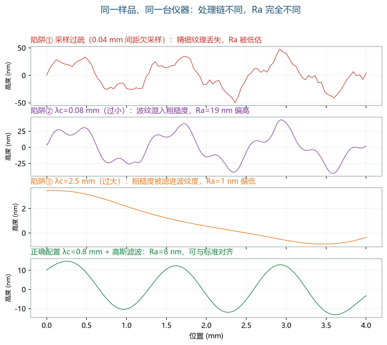
Stringing the four pitfalls together yields a universal working discipline for roughness measurement: agree first, measure second. The wavelength chain (λs, λc), the evaluation length, the sampling density, and the measurement window — all four go into the inspection specification before measuring, and all four are attached to the report. Meet this discipline and roughness data becomes comparable across instruments and laboratories; fail it and the parameter numbers themselves carry no engineering meaning. On the product side, optical techniques such as white-light interferometry and chromatic confocal make this discipline easier: both area imaging and point-by-point scanning support fixed, parameterized configurations — see "Chromatic Confocal vs. White-Light Interferometry vs. Stylus Profilometry" for a route comparison.
About Acuitik
Acuitik specializes in optical precision measurement technology. Its core products are reflectance-based film thickness gauges, ellipsometers, and OEM film thickness sensors featuring "non-contact, non-destructive, sub-nanometer accuracy":
- Industrial film thickness measurement NS series: NS-20 manual, NS-30 automated Mapping, NS-Micro microscopic, NS-Touch curved-surface, NS-HR thick-film, NS-100 high-speed line-scan
- Research-grade measurement ES series: ES-Tenso ellipsometer, ES-Primo multi-wavelength ellipsometer (for ultrathin films and complex multilayers), plus the NS-Vista dual-channel and NS-Flex portable multimodal units
- OEM film thickness sensors: multi-point nanoscale film thickness, NS-HR thick-film, and NS-Micro microscopic sensor modules, supporting Modbus / OPC UA for integration with PLC and MES, with an SDK provided
The instruments are metrologically certified by the National Institute of Metrology of China and the Shanghai Institute of Measurement and Testing Technology, and Acuitik participated in drafting the group standard T/CIET 2298-2026 "Calibration Specification for Thin-Film Interference Film Thickness Measurement Systems". For more selection guides and application notes, please visit the Acuitik official website.