Confocal Unstable, Sectioning Too Slow? It Is Time to Upgrade Hard Coating Thickness Monitoring
In automotive electronics, semiconductor chips, display panels, PCBs, and precision optical components, hard coatings are widely used to improve a product's wear resistance, scratch resistance, chemical resistance, and surface reliability.
The coating looks thin, yet it directly affects product performance.
Too thin, and the protective performance is inadequate; too thick, and it can bring increased internal stress, cracking, reduced adhesion, cosmetic abnormalities, and higher material costs.
Hard coating thickness therefore cannot simply be "roughly measured" — it needs to be monitored accurately, quickly, and stably.
As manufacturing processes become ever finer, customer attention has shifted from "is there a coating" to:
Is the thickness accurate? Is the batch stable? Is the whole part uniform? When the process changes by a few tens of nanometers, can it be detected in time?
Traditional measurement methods, too, are beginning to face new challenges.

图1| Hard Coating广泛应用于汽车电子、半导体芯片、显示面板、PCB、精密光学器件及透明保护材料等领域。涂层厚度直接影响产品的耐磨性、抗刮擦性、附着力和长期可靠性。
1. Why Does Hard Coating Thickness Matter More and More?
In the past, when products tolerated larger thickness variation, companies typically only needed to confirm that the coating was within a rough range.
But as end products move toward thinner, lighter, more precise, and highly reliable designs, the hard coating process window keeps narrowing.
The questions companies must answer are also becoming more specific:
- Is the thickness consistent between different batches?
- Is the same part uniform from center to edge?
- After adjusting coating amount, spray speed, or curing conditions, how much did the thickness change?
- Can process drift of tens of nanometers be detected in time?
- Can inspection results feed back to the production floor quickly?
- Can the measurement data be used to analyze yield and equipment condition?
Relying only on micron-level judgment or destructive testing of a small number of sampled parts can no longer meet these requirements.
Hard coating thickness measurement is evolving from simple "result confirmation" into a genuine process control tool.
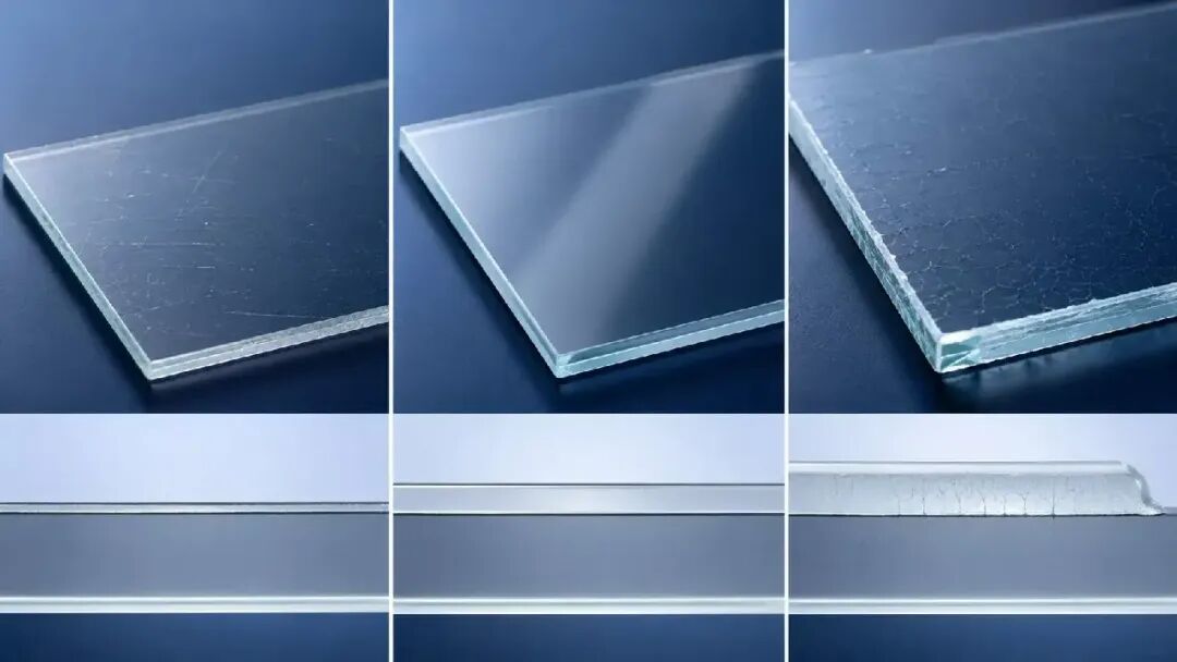
图2| Hard Coating厚度并非越厚越好。涂层过薄可能导致耐磨和防护性能不足;涂层过厚则可能增加内应力、开裂、附着力下降和材料成本,因此需要将厚度稳定控制在合理的工艺窗口内。
2. Chromatic Confocal Can Measure Thickness — Why Are Thin Coatings Getting Harder to Measure?
Chromatic confocal (spectral confocal) is a common non-contact technique for displacement and thickness measurement.
During measurement, the probe focuses different wavelengths of light at different axial positions; by identifying the positions of the reflection peaks from the sample's top and bottom surfaces, it computes the distance between the two interfaces and thereby obtains the transparent layer's thickness.
This method is suitable for surface height, profile, and thickness measurement of certain transparent materials.
But in thin transparent hard coating measurement, chromatic confocal results are easily affected by the interface-peak separation capability and the sample's surface condition.
1. The Top and Bottom Interface Signals of Thin Coatings Are Hard to Fully Separate
When measuring a transparent coating chromatic-confocally, the system must simultaneously identify the reflection signals from the coating's top surface and from the coating–substrate interface.
When the hard coating is thin, the two interfaces are very close axially; the two signal peaks may partially overlap, or even appear as one broadened peak.
At that point, the measurement result is easily affected by:
- the probe's axial resolution capability;
- reflection peak width;
- the peak-identification algorithm;
- algorithm threshold settings;
- the sample's reflectivity;
- the signal-to-noise ratio (SNR) of the return signal.
As the coating thickness approaches the system's interface separation capability, even when the device does output a thickness result, the values obtained from repeated measurements may fluctuate noticeably.
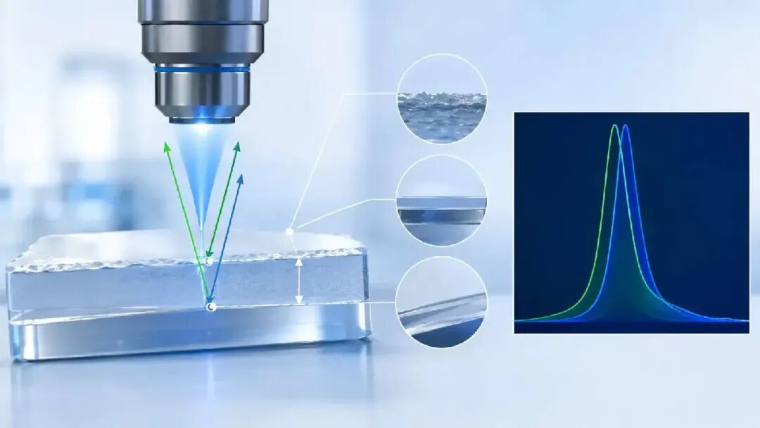
图3| 光谱共焦通过识别涂层上、下界面的反射峰计算厚度。当Hard Coating较薄时,两个界面峰可能非常接近并发生部分重叠,从而增加峰值识别和厚度计算的难度。
2. Strict Requirements on Coating Surface Flatness
The surface of a real hard coating sample is not always an ideal plane.
Spray texture, orange peel, local particles, slight warp, surface tilt, and local thickness undulation can all change the intensity and peak shape of the returned light.
When tilt or surface undulation exists at the measurement location, the reflection signal received by the chromatic confocal probe may weaken, and the positions and shapes of the top and bottom interface peaks may change accordingly.
For standard samples with relatively flat surfaces and stable reflection conditions, chromatic confocal can usually obtain clear interface signals.
But when the object becomes an actually coated, sprayed, or cured hard coating sample, changes in surface condition can directly affect the thickness result.
Therefore, when using chromatic confocal to measure hard coatings, closer attention is usually needed to:
- whether the sample is placed level;
- whether the measurement area is flat enough;
- whether the surface shows orange peel or obvious texture;
- whether particles or local defects exist at the measurement location;
- whether the top and bottom interface peaks are clear enough;
- whether the signal quality is consistent across different measurement positions.
3. Repeatability Is Easily Affected by Sample Condition
For process monitoring, the device must not only produce a thickness value — it must also produce stable results when the same position is measured repeatedly.
Chromatic confocal thickness results depend on locating the positions of the top and bottom interface peaks.
When the two peaks are close, the peak shapes change, or the return signal is weak, the algorithm may identify somewhat different peak positions each time, causing repeated measurement results to fluctuate.
Common factors affecting repeatability include:
- the tilt angle changing after the sample is replaced;
- slight surface undulation at the measurement position;
- uneven reflectivity of the coating surface;
- partial overlap of the top and bottom interface peaks;
- local roughness or scattering altering the return signal;
- small positional shifts of the measurement point.
Such fluctuation may not be noticeable when measuring thicker transparent layers, but when the customer needs to resolve process changes of a few tens of nanometers or less, it can become hard to distinguish:
whether the result change comes from a real thickness change, or from the repeatability fluctuation of the measurement itself.
4. Test Stability Depends on Good Measurement Conditions
In real production environments, sample state, placement, and measurement position can hardly remain perfectly consistent at all times.
If every test requires repeated re-leveling of the sample, hunting for flat areas, or optimizing the signal peaks, measurement efficiency and operational consistency will suffer.
Especially in batch sampling and production line monitoring, the test method needs to satisfy:
- measurement possible right after the sample is placed;
- essentially consistent results across different operators;
- small fluctuation for repeated measurements at the same position;
- comparability between different batches;
- no reliance on frequent manual adjustment and peak judgment.
For thin transparent hard coatings, when surface flatness is not ideal and the two interface peaks cannot be separated stably, chromatic confocal is prone to signal fluctuation, result jumping, or positions that cannot be measured stably.
Therefore, a measurement solution truly suited to hard coating process control must not only be able to output a thickness result — it must also offer good repeatability, stability, and adaptability to real sample conditions.
3. Cross-Sectioning Is Intuitive but Hardly Suited to Routine Line Use
Sectioning and cross-sectional microscopy show the coating cross-section directly, so they are often used for R&D validation, failure analysis, and method comparison.
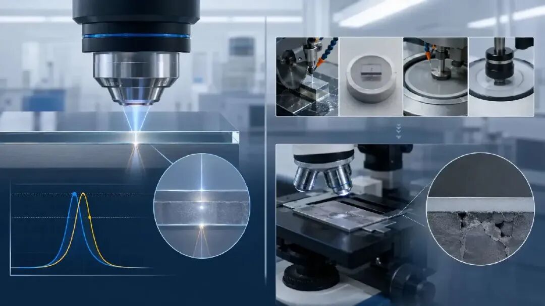
But its limitations are also very obvious.
First, sectioning destroys the sample; a measured part usually cannot continue in use.
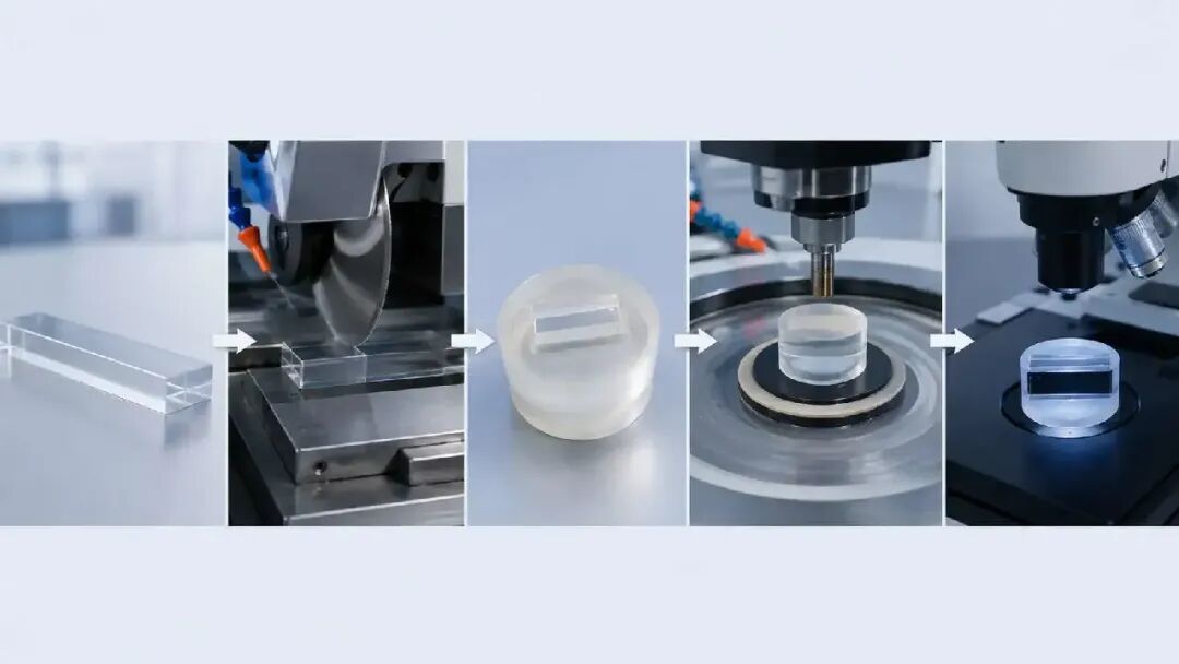
Second, a complete sample preparation cycle typically includes:
cutting, mounting, grinding, polishing, and microscopy.
The whole flow takes considerable time and places high demands on the operator's preparation experience.
If the cutting direction, grinding pressure, or polishing process is not properly controlled, it can also cause:
- tilted cross-sections;
- edge rounding;
- coating stretching;
- interface deformation;
- local delamination;
- polishing damage.
Any of these factors can affect the final thickness judgment.
More importantly, sectioning usually reveals only one or a few local cross-sections, and can hardly reflect the thickness uniformity of the whole part quickly.
Sectioning is therefore better suited as an R&D and validation tool than as a means of daily sampling, batch inspection, or real-time production line feedback.
4. From "Finding Two Interfaces" to "Analyzing the Whole Spectrum"
For thin hard coating measurement, Acuitik employs spectral reflectance interference film thickness measurement technology.
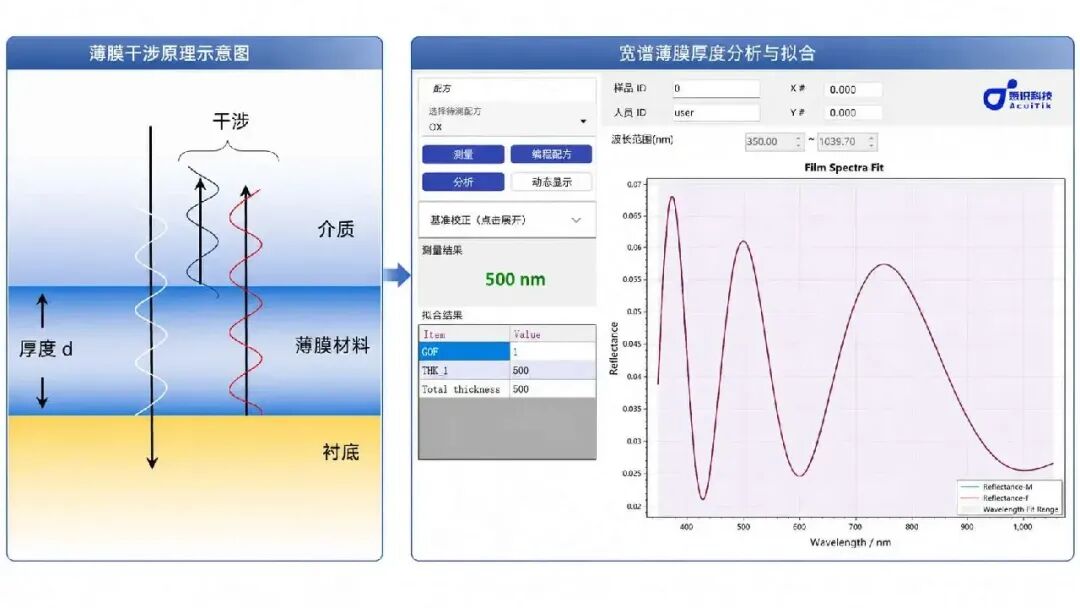
During measurement, a broadband light beam illuminates the hard coating surface.
Part of the light reflects at the air–coating interface; the rest enters the coating and reflects at the coating–substrate interface.
The two reflected beams have traveled different optical path lengths.
When they superpose, they form interference features in the reflectance spectrum that are related to the coating thickness and the material's optical properties.
The instrument collects the reflectance spectrum over the whole band and analyzes the measured spectrum with a thin-film optical model to compute the hard coating thickness.
Spectral reflectance interference measurement typically relies on:
- the Fresnel reflection principle;
- thin-film interference principles;
- multilayer optical models;
- the material's refractive index and extinction coefficient;
- fitting of the measured spectrum against the theoretical spectrum.
Unlike chromatic confocal, which depends on the position difference between two interface peaks, the optical interference method uses the reflectance spectrum information across the whole band.
Large numbers of wavelength data points jointly participate in the calculation, allowing the device to resolve tiny thickness differences from the overall spectral changes.
5. Why Is the Optical Interference Method Better Suited to Thin Transparent Hard Coatings?
Chromatic confocal versus optical interference is not a simple contest of "advanced versus backward."
The two observe different physical quantities and suit different problems.
But for thickness monitoring of thin transparent hard coatings, the optical interference method has clearer application advantages.
| Comparison item | Chromatic confocal | Spectral reflectance interference |
|---|---|---|
| Basic principle | Identify the two axial reflection peaks corresponding to the top and bottom interfaces | Analyze the thin-film interference spectrum across the whole band |
| Thin coating measurement | When too thin, the two interface peaks may approach or overlap | No need to resolve the two interfaces as independent height peaks |
| Thickness sensitivity | Affected by the probe's axial resolution and peak-identification capability | Tiny thickness changes alter spectral features across the whole band |
| Surface condition effects | Roughness, tilt, and scattering can change peak shapes | Roughness and scattering also affect the signal, but can be assessed together with whole-spectrum fitting quality |
| Material parameters | Transparent layer measurement requires refractive-index correction | Requires an optical model with n and k parameters matched to the sample |
| Measurement mode | Non-contact; single-point or scanning measurement | Non-contact; single-point, multi-point Mapping, and automation integration |
| Typical applications | Surface height, profile, and thicker transparent structures | Nanometer- to micrometer-scale transparent or semi-transparent film thickness analysis |
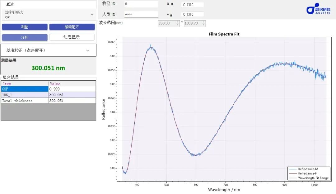
1. No Dependence on the Geometric Separation of Two Interface Peaks
The optical interference method does not first need two fully separated reflection peaks in the axial signal.
It analyzes the spectral features that the hard coating forms across the whole measurement band.
Even for a very thin coating, as long as the reflections from the top and bottom interfaces produce a recognizable optical response, thickness changes will show up in the spectrum.
This makes it especially suitable for thin transparent coatings that interface-separation methods struggle to measure stably.
2. Tiny Thickness Changes Act on the Whole Spectrum
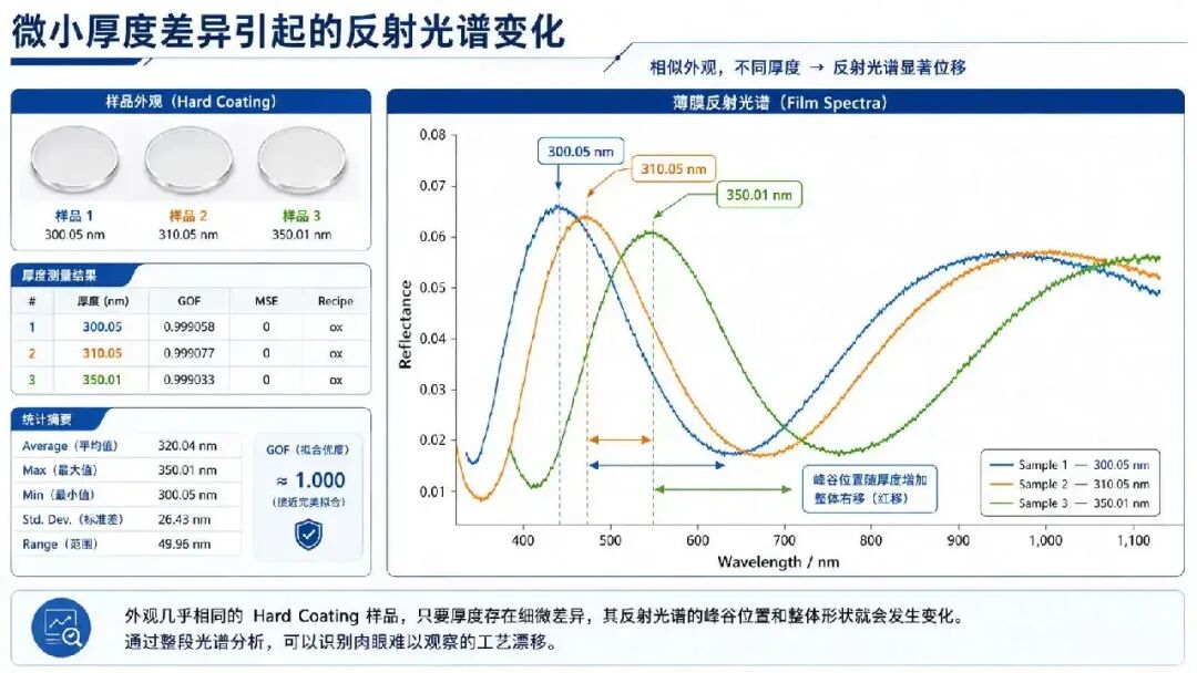
When the hard coating thickness changes, the peak and valley positions, phase, and overall shape of the reflectance spectrum all change accordingly.
The device does not judge thickness from any single data point; large numbers of wavelength data points jointly participate in the calculation.
Therefore, when the following conditions are met, the optical interference method can resolve nanometer-level thickness changes:
- the sample is sufficiently transparent or semi-transparent;
- the top and bottom interfaces produce effective reflection;
- the material's optical parameters are set reasonably;
- the film model matches the real sample structure;
- the spectral signal-to-noise ratio is good;
- surface scattering and absorption are not excessive.
A special note here:
"Nanometer-level measurement capability" more precisely refers to the ability to resolve and repeatably monitor nanometer-level thickness differences. Absolute accuracy must still be verified against real samples, taking into account the material, substrate, and surface condition.
3. A Different Kind of Dependence on Sample Flatness
Chromatic confocal must accurately locate two axial reflection peaks.
Therefore, peak-shape changes caused by local tilt, roughness, and scattering can directly affect the determination of interface positions.
The optical interference method does not treat the top and bottom interfaces as two independent height peaks; it computes the film thickness from the whole reflectance spectrum.
Therefore, in the presence of slight surface texture, local undulation, or slight tilt, the optical interference method generally retains better thin-film thickness analysis potential.
But this does not mean the optical interference method is completely immune to surface condition.
Interference features can still weaken if the sample has:
- excessive surface roughness;
- overly strong scattering;
- high coating absorption;
- severely non-uniform films;
- large numbers of particles on the sample surface;
- too much thickness variation within the spot.
Therefore, Acuitik combines the measured spectrum, fitting quality, repeatability, and multi-point results to comprehensively judge whether a sample is suitable for measurement, rather than simply outputting a thickness number devoid of quality assessment.
4. Non-Contact, Non-Destructive, Suitable for Repeated Measurement
The measurement process requires neither cutting the sample nor probe contact with the coating.
The same part can be measured repeatedly at different process stages:
- before coating;
- after coating;
- after pre-cure;
- after full cure;
- after reliability testing.
Through repeated measurement, thickness changes across the entire process can be observed.
For high-value chips, automotive electronics parts, precision optical components, display cover plates, and PCB products, inspection losses can be significantly reduced.
5. No Complex Sample Preparation, Faster Result Feedback
Spectrum acquisition and thickness analysis can begin as soon as the sample is placed.
No cutting, mounting, grinding, or polishing is needed — inspection cycles shorten significantly.
Whether for formulation screening in R&D or rapid sampling on the production floor, thickness results arrive sooner.
6. Beyond Measuring One Point: See the Thickness Distribution of the Whole Part
For large hard coating samples, a single measurement point can rarely represent the overall process.
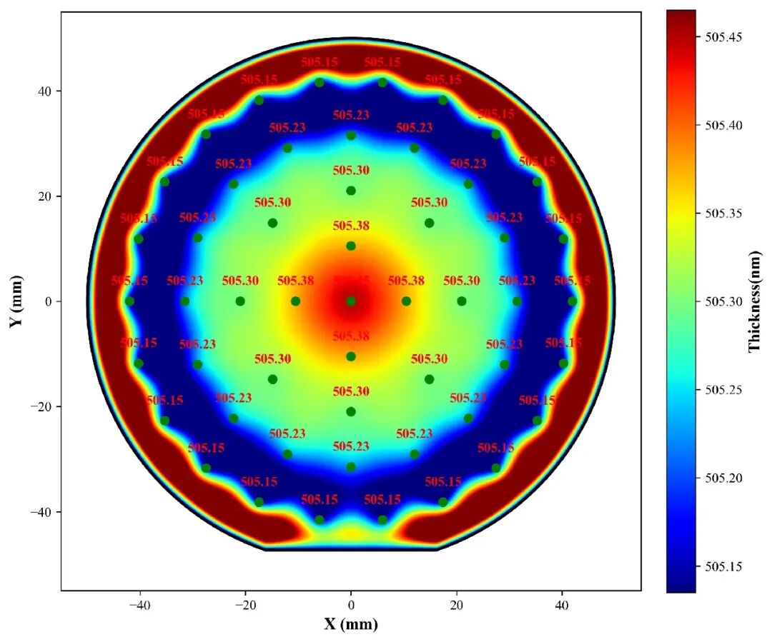
Acuitik's automated film thickness measurement equipment performs multi-point measurement at preset coordinates and outputs:
- thickness data at each point;
- average thickness;
- maximum and minimum values;
- range;
- standard deviation;
- point CV;
- 2D thickness Mapping;
- center-to-edge variation trends.
Mapping results make it easier to judge:
- whether the center is thick and the edge thin;
- whether spray accumulates locally;
- whether the coating direction produced a thickness gradient;
- whether the curing process created regional differences;
- whether batch-to-batch uniformity has changed;
- whether the thickness distribution improved after equipment parameters were adjusted.
For process engineers, Mapping brings not only a color map, but a dataset that helps locate process problems.
7. One Measurement Solution Covering Many Hard Coating Application Stages
Laboratory R&D
During formulation, coating parameter, and curing process development, quickly compare thickness changes across experimental conditions to accelerate material screening and process validation.
Incoming and Outgoing Inspection
Quickly measure samples from different batches to judge whether the coating thickness is within specification, keeping traceable inspection data.
In-Process Monitoring
Measure samples before and after key process steps to promptly detect thickness drift caused by changes in spray amount, coating speed, curing conditions, or equipment state.
Multi-Point Uniformity Evaluation
Obtain the whole-part thickness distribution through automated Mapping measurement, avoiding the use of single-point results to represent the entire part.
Automation and Inline Integration
According to production line requirements, it can realize:
- automatic positioning;
- automatic spectrum acquisition;
- automatic thickness computation;
- automatic pass/fail judgment;
- automatic data saving;
- automatic Mapping generation;
- communication with MES or a host computer.
This lays a reliable measurement foundation for subsequent closed-loop process control.

8. Hard Coating Applications Are Far Broader Than You Might Imagine
Hard coating is not the specialty material of any single industry; it is already widely used in:
- automotive displays, vehicle-mounted cameras, and automotive electronics parts;
- semiconductor chips, wafers, and advanced packaging structures;
- phones, tablets, foldables, and touch display products;
- protective coatings for PCBs, FPCs, and electronic components;
- optical lenses, transparent cover plates, and precision optical devices;
- surface hardening of plastic materials such as PET, PC, and PMMA;
- industrial panels, sensors, and high-reliability electronic products.
As products move toward thinner, lighter, more precise, and highly reliable designs, the importance of hard coating thickness control will keep rising.
9. The Real Advantage Is More Than "Measuring More Finely"
Whether a measurement method truly suits production cannot be judged solely by the highest precision on a specification sheet.
What matters more:
Can it inspect non-destructively?
Can it stably resolve subtle changes in thin coatings?
Can it reduce reliance on complex sample preparation?
Can it assess whether the measurement result is trustworthy?
Can it complete multi-point measurement quickly?
Can it monitor batch and process drift over the long term?
Can it be integrated into the production flow easily?
Acuitik specializes in high-precision, non-destructive optical thin-film measurement, building targeted optical measurement solutions based on different hard coating materials, substrate structures, thickness ranges, and measurement takt times.
From laboratory R&D and sample inspection to automated Mapping and inline production line monitoring, we hope to help customers turn every thickness measurement into data that can truly guide production, improve processes, and raise yield.
Free Sample Testing
Different hard coatings differ in transparency, refractive index, absorption characteristics, surface condition, and substrate structure.
Whether an instrument suits a given sample cannot be judged from the material name alone; it needs to be verified with real spectra and repeated measurements.
Before equipment selection, Acuitik can provide, based on your actual samples:
- reflectance spectrum and interference feature analysis;
- hard coating thickness measurement;
- multiple repeatability tests;
- thickness comparison across different positions;
- thickness uniformity and Mapping analysis;
- recommendations for laboratory, automated, or inline measurement solutions.
Judge not only by equipment specifications, but by measurement results on real samples.
You are welcome to send us your hard coating samples — let spectra, repeatability, and Mapping data verify the equipment's capability.
Acuitik
Dedicated to high-precision, non-destructive optical thin-film measurement